

Extraction of Surface Roughness Symbol from Technical Drawings
Analyzing Technical Drawings requires the understanding of many engineering terms. One of these parameters is the Surface Roughness symbol which defines the smoothness of a surface. Smooth Surfaces are required for many applications. For example, in the context of contact bearings, it is vital to achieving minimal friction on the surface to improve bearing efficiency. Sometimes it can also be just for producing a shiny surface for a better product outlook. In manufacturing, reaching a high surface finish can be very critical, depending on the application of the part. For high-precision medical equipment, this can turn out to be the most significant parameter for the proper operation of the component. Achieving these smooth surfaces, requires the part to be finished in a post-processing step.
Why OCR is Not Enough
Manually analysing Engineering Drawings is time-consuming and involves the risk of human error. Automatically analysing them is the dream for the industry. For this task, Optical Character Recognition (OCR) is insufficient. Even when traditional OCR solutions extract the text elements correctly, the interpretation depends of each value still depends on the positions of text elements relative to the Surface symbol. To add to the complexity, there’re several standards that define the surface roughness, each with its multiple variations. Understanding the meaning of the surface roughness with traditional OCR is almost impossible.
New Release: Surface Roughness Extraction
Werk24 now offers a new feature: extraction oof Surface Roughnesses from Technical Drawings. We uses state-of-the-art AI algorithms to grasp the meaning of Surface Roughness symbol on Technical Drawings. There are several key challenges we tackled:
1. Detection of Text Position & Correct interpretation
Our solution detects the relative position of each text element to the Surface Roughness symbol, and interprets the value accordingly. As shown in the image, Werk24 knows whether the “0.8” describes the material allowance or the average Ra value - OCR would not.
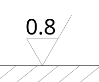
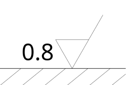
The left image specified an average of Ra0.8, while the right image gives a 0.8mm machining allowance.
2. Unifying Different ISO & ANSI Standards and Their Different Releases into Standard JSON and String Result
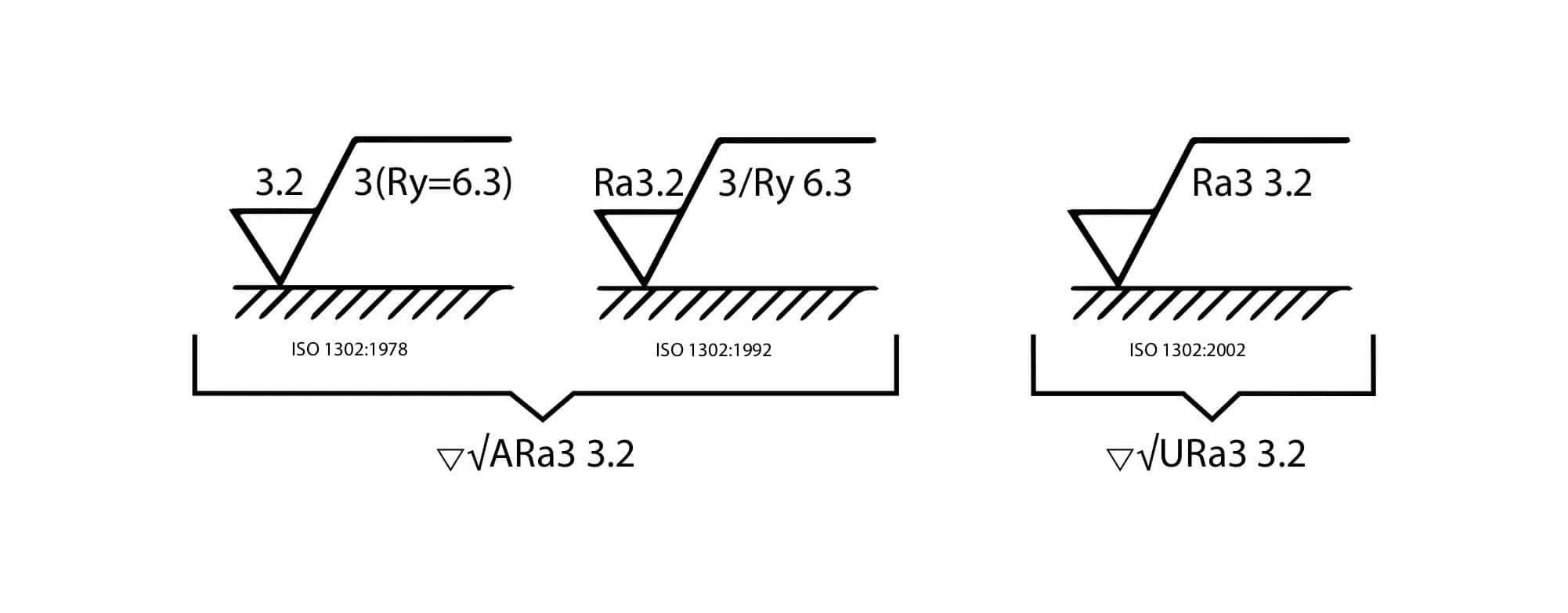
Our solution understands the different ISO and ANSI standards in their different releases and returns Surface Roughness in the standardized format. As shown in the image, Werk24 understands the ISO 1302 in its 1978, 1992 and 2002 release, and unifies them in the format meaningful for modern applications.
Our API produces results in an easy-to-use JSON-format as well as a simplified string representation that conveys the meaning to the user, regardless of the input standard. The following image depicts similar surface roughness definitions in the ISO standard in its 1978, 1992 and 2002 versions and the one single format by Werk24. Please note, that the 1978 and 1992 versions specify the Ra value as average, and the 2002 version specifies it as upper limit. In addition, the Ry specifications have been abolished in the 2002 version.
This demonstrates the complexity of dealing with Surface Roughness and the advantages we offer over the OCR technology.