
Why Extracting Outer Dimensions from Technical Drawings is Challenging
Extracting Outer Dimensions (or External Dimensions, Bounding Box, Bounding Cylindar) is strongly demanded in many industry scenarios, such as manufacturing platform pricing, machine fit analysis for additive manufacturing, material ordering, etc. Although this feature seems effortless, it is in reality extremely challenging when it is an automated solution based on merely the Technical Drawing.
“How is this more difficult than reading the largest dimensions on the drawing?” Many asks. In fact, in many cases, determining the bounding box requires a correct interpretation of all measures and radii in its meaning as well as the association to each other in the whole 3D geometry.
Werk24’s solution interprets all measures and radii as well as pixel information of the 2D outer contour to create a 3D approximation of the part. In this method, we reliably offer the outer dimension in many corner cases without discrepancies or misinterpretations.
Cases when Outer Dimension is non-trivial:
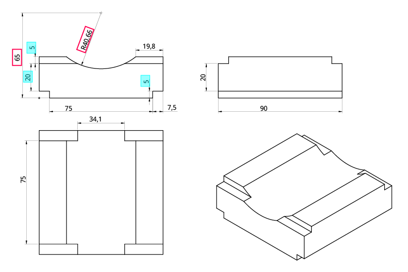
Largest number is not outer dimension
The largest measure 65mm on the drawing will lead you to believe the part was 65mm high. In fact, the height is only 30mm (5+20+5), which requires the technical solution to extract all the 3 measures in Y dimension and interpret them in relation to sum together. The same challenge goes to the Radius 40.66mm, which defines a concave and therefore must be ignored in outer dimensions calculation in this geometry. Werk24’s solution can achieve all of this, as it is not simply getting OCR results but interpreting them in relation to each other in 3D.
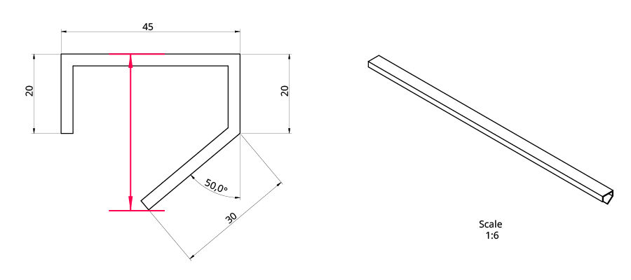
Require extra calculation
Sometimes, determining the bounding box requires the consideration of mulitple dimensions. For example, in this drawing, the height is not explicitly given and must be determined by calculating the missing vertical components through another measure (30mm) and the angle (50 degree). In this case, Werk24 can offers high-quality approximation of the height through the outer contour result from our CADApprox 2D solution.
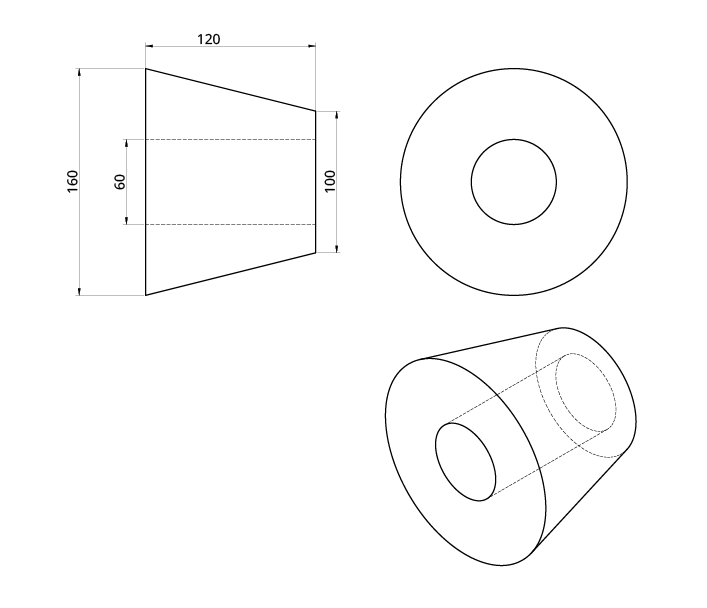
Dimension implied in 3D geometry
Finally, the 3D geometry can contain dimension that is not specified on the drawing. Here, for example, the depth of the part is missing on both sectional views. The only way to get it is to understand it’s a rotational piece by putting the two sectional together and interpret the 3D shape correctly. Werk24's Artificial Intelligence analyses all sectional views and understands it as a round part with a depth of 160mm.
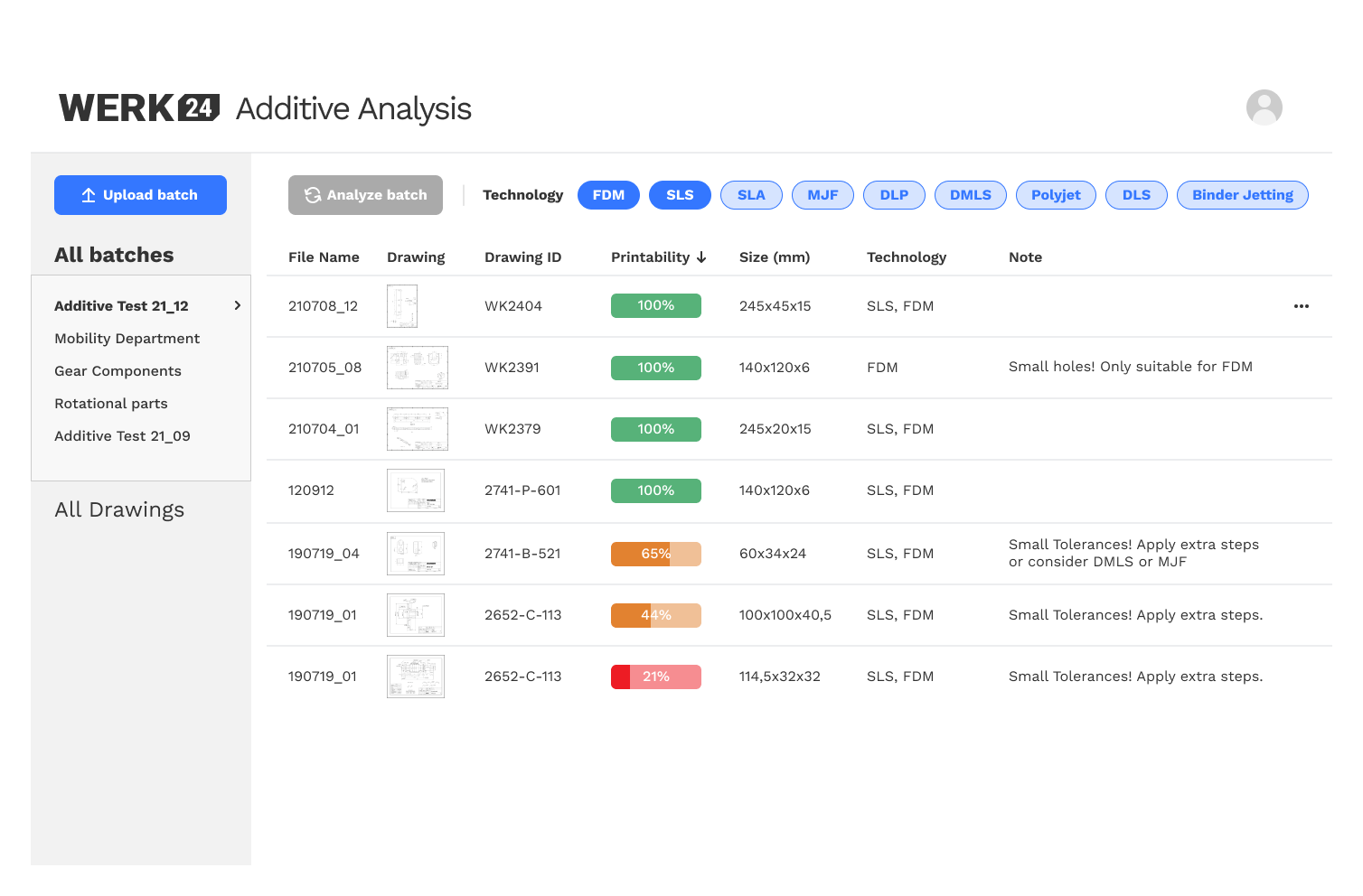
Outer Dimension Application
With its reliable solution to interpret all measures and radii and create 3D approximation of the part based on only Technical Drawing, Werk24 furthered the offering in our Additive Analysis.