Measures: Need to Know for Getting Useful Parts
Measures describe the ideal lengths and the max. allowed deviation before the part becomes useless.
A multitude of different measurement and toleration systems exist (we simplify the handling).
Ignoring measures will result in parts that ‘look’ correct but are useless (e.g., 2 parts will not fit together). We provide a short description of what you need to know for getting useful parts.
There are probably as many ways to define Measures as there are drafters. We do our best to interpret as many as possible and return them to you in a consistent way. Below, table gives you a brief overview of the most common measure systems. This solely provides an overview of the most frequently used measure systems. We manage the complexity for you and return the same response, independently of which measure system the drafter chose.
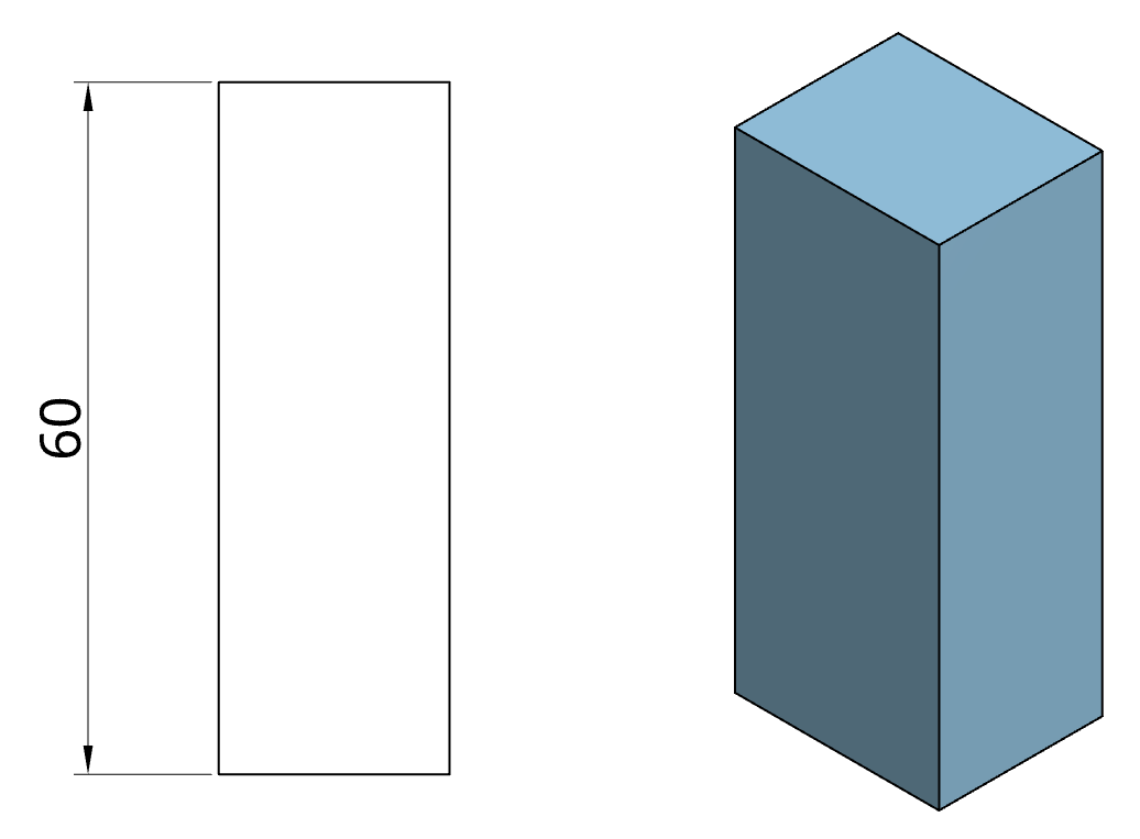
Method 1 (mainly European)
DIN 406-11 defines two methods for annotating simple measures. In Method 1, the measure labels are following the two main reading directions: (i) bottom up and (ii) from left to right. This method is mainly used in European countries.
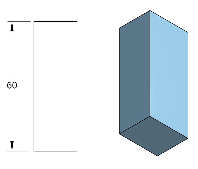
Method 2 (mainly US-American)
Method 2 allows the drafter to draw all labels parallel to the title block. This is mainly used in the United States of America.
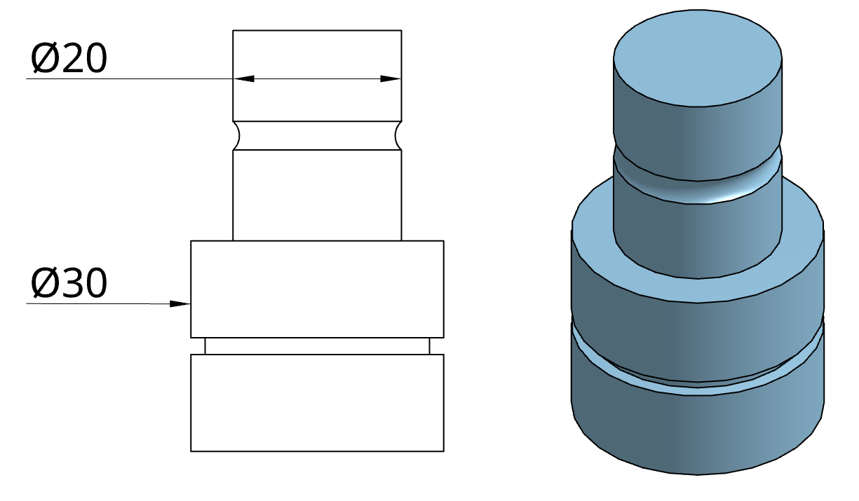
Diameter
Diameter Measures can be annotated with only one measure arrow and can be located at the inside or outside of the element. We look at the drawing and find the most likely interpretation for you.
Spherical Diameter
The symbol 'SØ' is used to denote the diameter of a spherical surface. For example, if a spherical surface is labeled as 'SØ30', it means that its diameter is 30 millimeters.
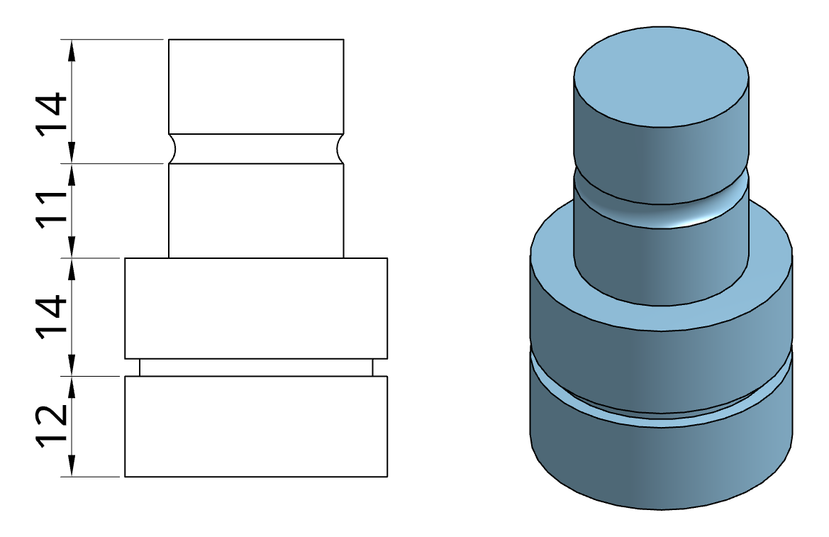
Chain measures
Chain measures can improve the readability of the drawings by using the same measure line for adjacent measures.
Ascending measures
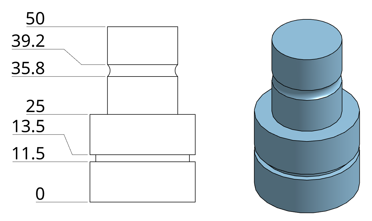
The ascending dimensioning system is typically chosen when the number of measures increases further, and space becomes a problem. The system works similar to a measuring tape by defining an origin and annotating the distance of a whole range of points from this origin.
Angle Dimension
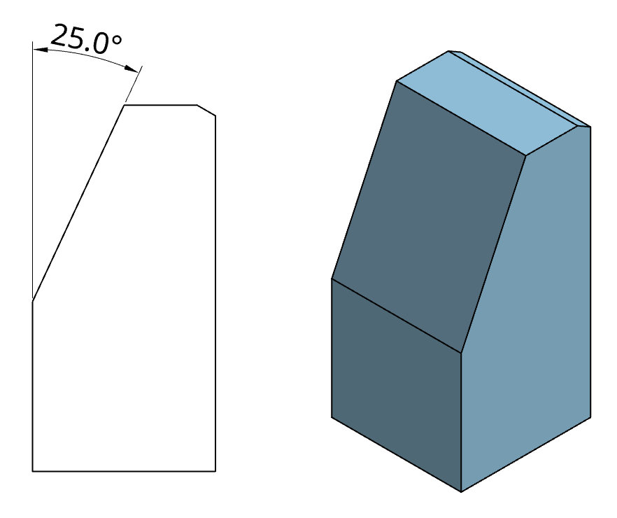
The Angular Dimension is used to show angles between two edges. It is shown by a circular dimension arc which has its centre at the vertex of the angle.
Chamfer Dimension
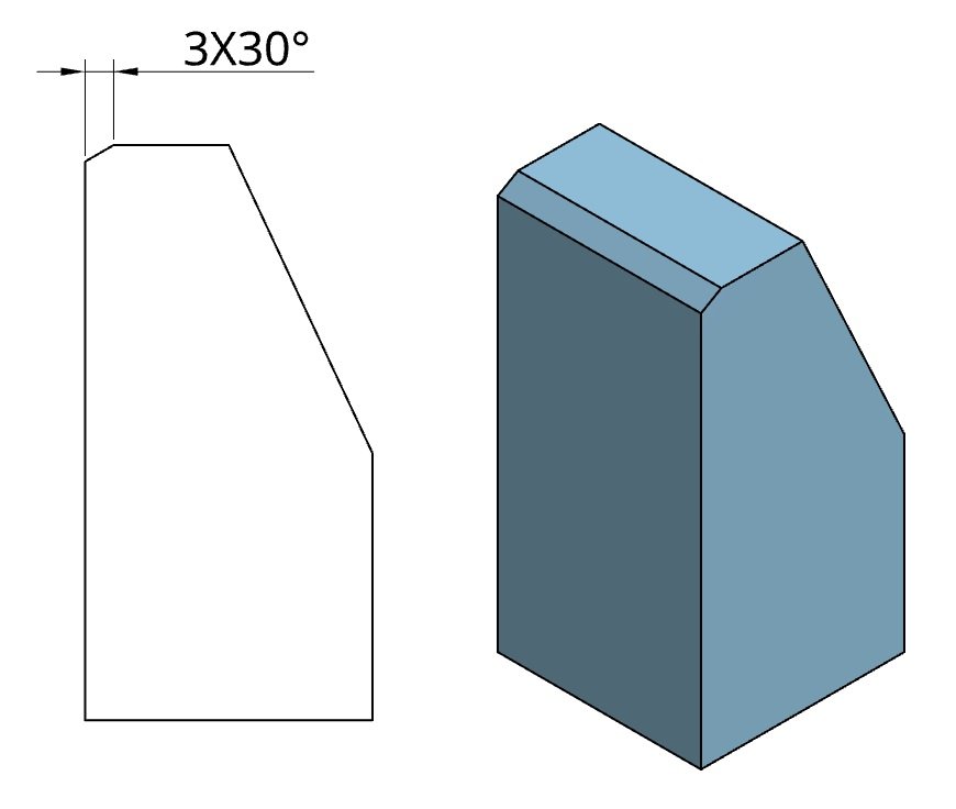
The Chamfer dimension is used to annotate the chamfers given on the edges of the part. It has two important features, the width and the angle of the chamfer. For special case of 45° chamfer the symbol ´C´ is used along with the width of the chamfer.


