Symbols: Need to Know for Dispelling Uncertainty in Drawings
The following is a short list of symbols that normally appear on a Technical Drawing and need understanding. We offer you our tips which we believe are useful for dispelling uncertainty by comparing the symbol with its graphic representation.
Radius ‘R’
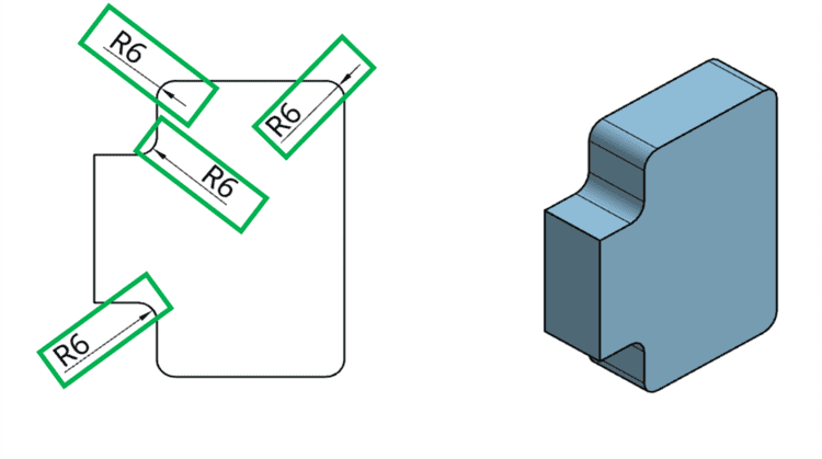
Radius can be for the inside and outside curved surface on the part. They are also used to show the fillets given to strengthen the edges at connecting faces. A radius dimension is preceded by an `R´. Arcs are also dimensioned on drawing with a radius. For Example, R6 means the circle has a radius of 6mm.
Spherical Radius ‘SR’
The abbreviation 'SR' is used to denote the radius of a spherical surface. For example, if a spherical surface is labeled as 'SR30', it means that its radius is 30 millimeters.
Diameter ‘Ø’
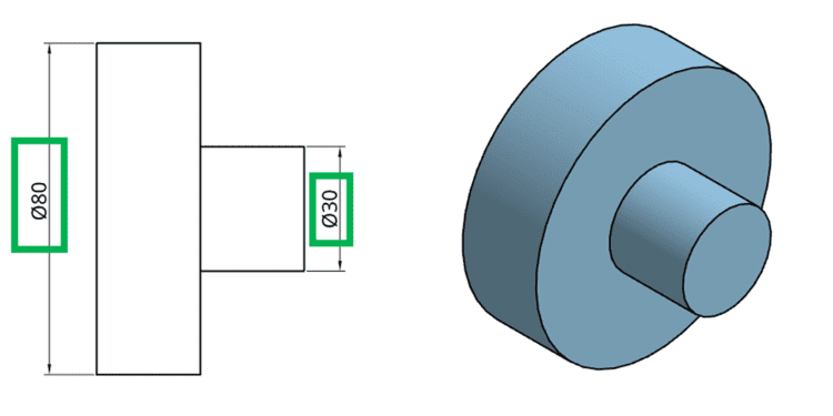
A diameter dimension is represented on a drawing with the ‘Ø’ symbol preceding the value as shown in the below figure. Circles on a drawing are dimensioned with a diameter. For example, Ø80 means that the diameter of a circle is 80mm.
Spherical Diameter ‘SØ’
‘SØ’ is used to represent the diameter of a spherical surface. For Example, SØ30 means the spherical surface has a diameter of 30mm.
Square ‘□’
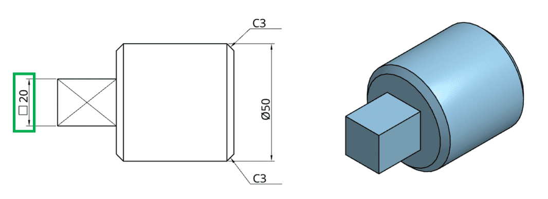
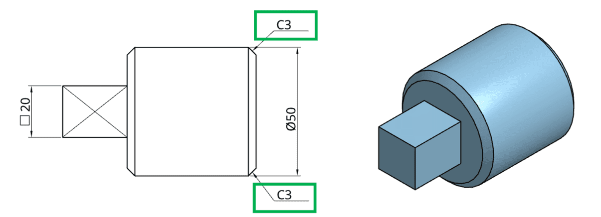
The symbol ‘□’ is used to show the square section of a part. For example, □20, means it is a square section with each side of 20mm.
Thickness ‘t’
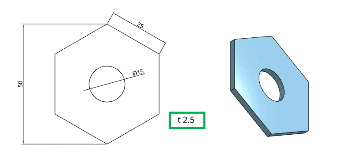
The letter ‘t’ is used to denote the thickness of the sheet metal part. For example, t2.5 means the sheet metal part is 2.5mm thick.
45-Degree Chamfer ‘C’
The letter ‘C’ is used to show the chamfer of 45°. For example, C3, means a chamfer of 3mm width and 45° angle.


